Site Specific TEM Sample Preparation
Advances in aluminium sample preparation – Xenon plasma FIB
Introduction
The introduction of xenon plasma focused ion beam, (P-FIB) technology offers aluminium researchers a new range of options for TEM and atom probe sample preparation not previously possible by gallium ion FIB.
Aluminium metallurgists have been forced to remain in the pre-FIB era, having to rely of electropolishing, ion polishing and microtome sample preparation routes. These techniques can produce large area TEM samples with relative speed once set up but neither route offers the site specificity of FIB. Furthermore, these techniques come with inherent challenges such as induced mechanical damage for microtome samples, preferential etching of precipitates during electro polishing and long process times for ion polishing. Electro polishing and microtome are very much reliant on the skill of the metallurgist to produce consistent samples and both techniques have a low success rate when compared to FIB preparation.
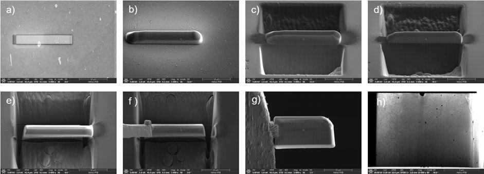
Figure 1 - lift-out procedure for aluminium in the P-FIB. (a) electron beam platinum deposition, (b) ion beam platinum deposition, (c) rough milling to form a lamella, (d) sample cleaning and thinning, (e) undercutting the sample, (f) welding the transfer probe and lifting the sample onto a grid, (g) the sample welded on the grid, (h) the thinned TEM sample observed by in-situ STEM detector.
Gallium FIB TEM sample preparation is not suitable for aluminium sample preparation due to gallium’s affinity to aluminium. Microstructurally this affinity to aluminium manifests itself as the segregation of gallium-based precipitates at the grain boundaries of aluminium TEM samples. Unocic, et.al. published an in-depth study of these effects [1]. They also showed how a hybrid approach could be taken using argon ions to clean gallium prepared TEM lamellar [1]. Although this approach works, with a total preparation time of around 5 hours per sample, it is not a time or cost-effective approach.
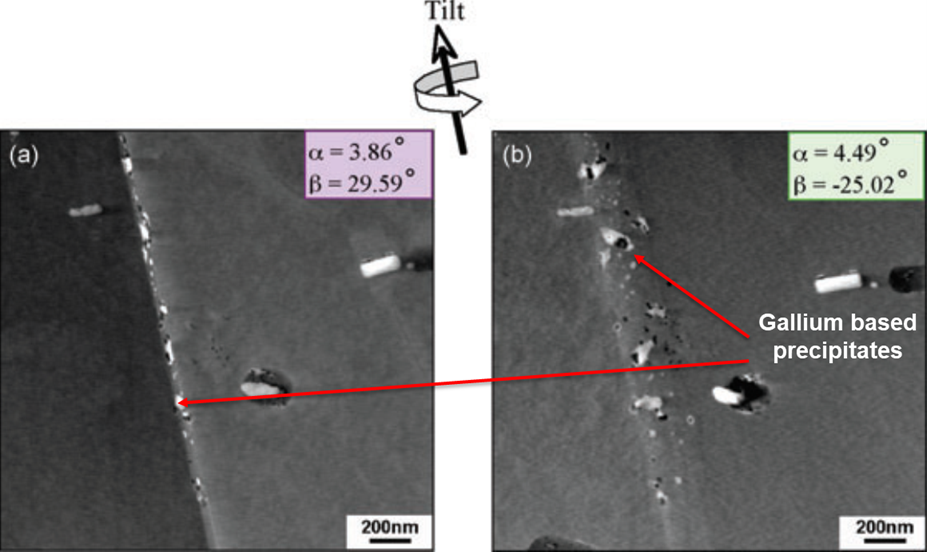
Figure 2 - DF STEM micrographs showing the presence of distinct gallium clusters within grain boundaries distributed in a discontinuous manner along a grain boundary viewed in (a) edge-on and (b) inclined orientations [1].
Xenon plasma FIB systems do not suffer from the implantation and segregation issues previously found with gallium FIB. What is more, xenon plasma can be used at much higher currents with a small milling spot size maintained; this allows for very quick material removal. The atomic mass and radius of xenon is significantly larger than that of gallium - this has a twofold effect; the sputter yield of xenon is higher than that of gallium and the implantation effect of xenon is less. These interactions can be modelled using stopping range of ions in matter (SRIM) simulations, (see figure 3).
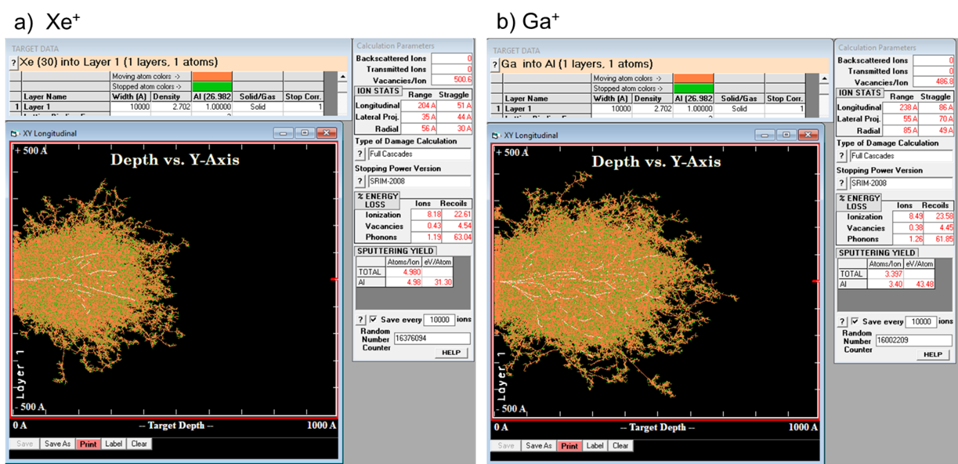
Figure 3 - SRIM simulations of 1000 Xe+ and Ga+ ions implanted into aluminium. a) Xenon ions implanted into aluminium were the ion range is 204 Å and sputtering yield 4.9 Atoms/ion, b) gallium ion implantation range 238 Å and sputtering yield 3.4 Atoms/ion.
The simulations show xenon can remove more material from aluminium whilst causing less damage. Comparable results have also been validated through high resolution TEM studies in silicon [2].
This combination of low damage and high current allows the more routine use of more complex lift out strategies (EBSD informed lift outs), larger cross sections (up to 900 µm width), and large volume serial sectioning studies (200 x 100 x 100 µm.)
Taking a similar time compared to standard TEM sample preparation, (approximately 30 minutes extra), EBSD informed in-plane lift outs are becoming a more popular approach for TEM lift outs. The advantage of in-plane lift outs is that the crystal orientation of the sample can be pre-determined. This allows very minimal tilt to be used in the TEM to get to the zone axis, as such high resolution TEM is easier to achieve (see figure 4 for example.) Furthermore, the orientation relationship of the parent phase and precipitates are easier to calculate and dislocation density measurements are more easily compared between specimens.
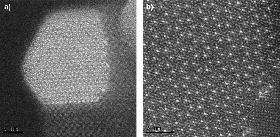
Figure 4 - Example lattice resolution images of aluminium and Q phase precipitates. sample prepared by in-plane P-FIB lift out [credit: Simon Hogg 2019]
References
[1] K. Unocic, M. Mills, and G. Daehn, “Effect of gallium focused ion beam milling on preparation of aluminum thin foils,” J. Microsc., vol. 240, no. June 2009, pp. 227–238, 2019.
[2] R. Kelley, K. Song, B. Van Leer, D. Wall, and L. Kwakman, “Xe+ FIB Milling and Measurement of Amorphous Silicon Damage,” Microsc. Microanal., vol. 19, no. Suppl 2, pp. 862–863, 2013.