Technology
Redundancy and reliability
Conventional points operating equipment has single points of failure. If the equipment fails, then the switch remains in position until personnel are sent on track to make repairs. During this time the switch cannot be moved and (at best) only one route is available through the switch. This results in operational problems and delays to passengers.
One method of introducing fault tolerance is to use multiple redundant actuators. Aircraft have 2 or 3 actuators driving each control surface. Should one or even two actuators fail, the third is available to allow continued safe operation. It would be possible to use two or more convention point machines on a single switch; however, this would not provide the redundancy anticipated. Most conventional points operating equipment includes the locking device within the actuator. If an actuator failed in the locked position, the second actuator would not be able to overcome this lock.
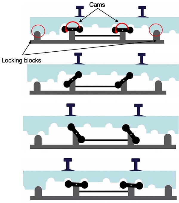
To allow multiple actuators to operate the switch, the Repoint system introduces “passive” locking; any operational actuator can release the locking function of a failed actuator. The mechanism uses cams to lift the switch rails out of one locked position, translate them across and drop them into the opposite locked position. The switch rails and the “hopper” part of the actuator follow a semi-circular arc. When in the lowered position, the switch rails rest on “locking blocks” and cannot move laterally. Any one actuator is capable of lifting the hopper and switch rails out of the down and locked position, translating them across and dropping them into the down and locked position on the opposite side.
For the Repoint Light design, the Repoint actuators have been adapted to function with a conventional switch rail arrangement (Figure 2). These actuators can be isolated individually when faulty, and the switch operates using the remaining channels until repair is possible, without a reduction in system performance.
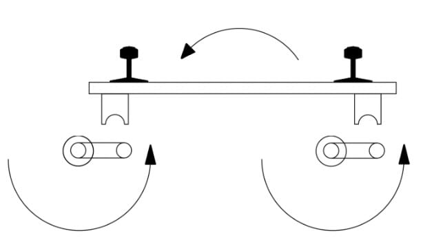
The main design change from a conventional switch actuation mechanism is that the Repoint Light actuators operate the switch rails through a two dimensional arc, lifting them out of register before traversing them and then lowering them in the opposite register (Figure 3 and Figure 4).
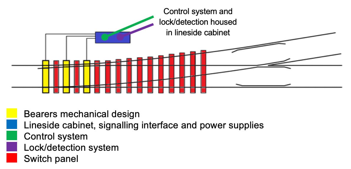
There are 3 actuator bearers in the Repoint Light demonstrator. The actuators are positioned at bearer positions 1, 3 and 5, counted from the switch toe. The three actuator bearers are similar, with alternative assembly of the cam mechanism to provide differing cam lengths in each of the 3 bearers. Figure 5 below shows the layout of the Repoint demonstrator switch panel.
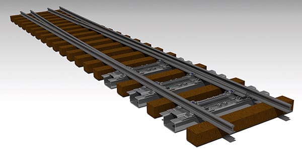
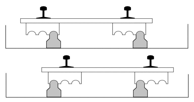
Figure 6 shows the Repoint actuator bearer. The entire operating mechanism is housed within the hollow bearer. There is no equipment beyond the ends of the bearer, nor any equipment above the bearer top between the rails. The Repoint bearer uses off the shelf half baseplates for securing the stock rails.
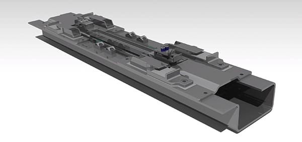
The switch rail mounting is a cradle design, positively holding the rail in the lateral sense. The cradle design allows for the changing radius and position of the switch rail in all axes through the motion of the switch. The rail is clamped down into the cradle with allowance made for thermal expansion. The switch rail cradles are an integral part of the “hopper”. This component provides the function, provided by the stretcher bar in conventional designs, maintaining the open switch rail position. The hopper also transfers the train loads through the locking blocks to the bearer base when the switch is in either the normal or reverse positions. It is the hopper that is lifted and translated by the cams to provide the switching motion. Figure 6 shows the hopper, cams and locking blocks.
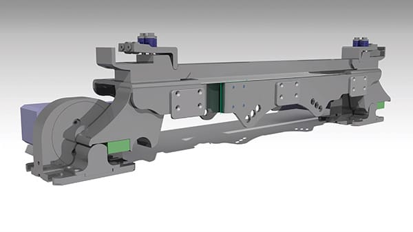
The motor and cam drive mechanism has 2 cams in each bearer, each independently driven by an electric motor. Cam position sensors are fitted to each cam, both to ensure synchronous movement, and to allow recalibration and self-checking following power outage.