About Additive Manufacturing
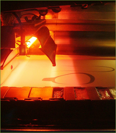
Powder Bed Fusion
The Powder Bed Fusion process includes the following commonly used printing techniques: Direct metal laser sintering (DMLS), Electron beam melting (EBM), Selective heat sintering (SHS), Selective laser melting (SLM) and Selective laser sintering (SLS).
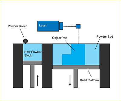
Powder bed fusion (PBF) methods use either a laser or electron beam to melt and fuse material powder together. Electron beam melting (EBM), methods require a vacuum but can be used with metals and alloys in the creation of functional parts. All PBF processes involve the spreading of the powder material over previous layers. There are different mechanisms to enable this, including a roller or a blade. A hopper or a reservoir below of aside the bed provides fresh material supply. Direct metal laser sintering (DMLS) is the same as SLS, but with the use of metals and not plastics. The process sinters the powder, layer by layer. Selective Heat Sintering differs from other processes by way of using a heated thermal print head to fuse powder material together. As before, layers are added with a roller in between fusion of layers. A platform lowers the model accordingly.
Powder Bed Fusion – Step by Step
- A layer, typically 0.1mm thick of material is spread over the build platform.
- A laser fuses the first layer or first cross section of the model.
- A new layer of powder is spread across the previous layer using a roller.
- Further layers or cross sections are fused and added.
- The process repeats until the entire model is created. Loose, unfused powder is remains in position but is removed during post processing.
Technical Info
Selective laser sintering (SLS) machines are made up of three components (Gibson et al., 2010): a heat source to fuse the material, a method to control this heat source and a mechanism to add new layers of material over the previous. The SLS process benefits from requiring no additional support structure, as the powder material provides adequate model support throughout the build process. The build platform is within a temperature controlled chamber, where the temperature is usually a few degrees below that of the material melting point, reducing the dependency of the laser to fuse layers together. The chamber is often filled with nitrogen to maximise oxidation and end quality of the model. Models require a cool down period to ensure a high tolerance and quality of fusion. Some machines monitor the temperature layer by layer and adapt the power and wattage of the laser respectively to improve quality.
Selective Laser Melting (SLM) Compared to SLS, SLM is often faster (Gibson et al., 2010), but requires the use of an inert gas, has higher energy costs and typically has a poor energy efficiency of 10 to 20 % (Gibson et al., 2010). The process uses either a roller or a blade to spread new layers of powder over previous layers. When a blade is sed, it is often vibrated to encourage a more even distribution of powder (Gibson et al., 2010). A hopper or a reservoir below or aside the bed provides a fresh material supply.
Selective Heat Sintering (SHS) uses a heated thermal printhead to fuse powder material together. As before, layers are added with a roller inbetween fusion of layers.The process is used in creating concept prototypes and less so structural components. The use of a thermal print head and not a laser benefits the process by reducing significantly the heat and power levels required. Thermoplastics powders are used and as before act as support material. The ‘Blue printer’ is a desktop 3D printer that uses the SHS technology, with a build chamber of 200mm x 160mm x 140mm, print speed of 2-3mm/hour and a layer thickness of 0.1mm (Blue Printer SHS , 2014).
Direct Metal Laser Sintering (DMLS) uses the same process as SLS, but with the use of metals and not plastic powders. The process sinters the powder, layer by layer and a range of engineering metals are available.
Electron Beam Melting (EBM) Layers are fused using an electron beam to melt metal powders. Machine manufacturer Arcam used electromagnetic coils to control the beam and a vacuum pressure of 1×10⁻⁵ mba (EBM Arcam , 2014). EBM provides models with very good strength properties due to an even temperature distribution of during fusion (Chua et al., 2010). The high quality and finish that the process allows for makes it suited to the manufacture of high standard parts used in aeroplanes and medical applications. The process offers a number of benefits over traditional methods of implant creation, including hip stem prosthesis (Agaruala, 1995). Compared to CNC machining, using EBM with titanium and a layer thickness of 0.1mm, can achieve better results, in an faster time and can reduce the cost by up to 35%.
Post processing requirements include removing excess powder and further cleaning and CNC work. One advantage and common aim of post processing is to increase the density and therefore the structural strength of a part. Liquid phase sintering is a method of melting the metal powder or powder combination in order to achieve homogenisation and a more continuous microstructure throughout the material, however, shrinking during the process must be accounted for. Hot isotactic pressing is another method to increase density; a vacuum sealed chamber is used to exert high pressures and temperatures of the material. Although this is an effective technique to improve strength, the trade-off is a longer and more expensive build time.
Machine Example:
|
Machine |
Area |
Layer Thickness |
Print Speed |
|
3S Systems ProX 500 |
381 x 330 x 457 mm |
0.08 - 0.15 mm |
2 litres/hr |
Materials
The Powder bed fusion process uses any powder based materials, but common metals and polymers used are:
SHS: Nylon DMLS, SLS, SLM: Stainless Steel, Titainium, Aluminium, Cobalt Chrome, Steel EBM: titanum, Cobalt Chrome, ss, al and copper (Materials Arcam, 2014).
Pros / Cons
Advantages:
- Relatively inexpensive
- Suitable for visual models and prototypes
- (SHS) Ability to integrate technology into small scale, office sized machine
- Powder acts as an integrated support structure
- Large range of material options
Disadvantages:
- Relatively slow speed (SHS)
- Lack of structural properties in materials
- Size limitations
- High power usage
- Finish is dependent on powder grain size